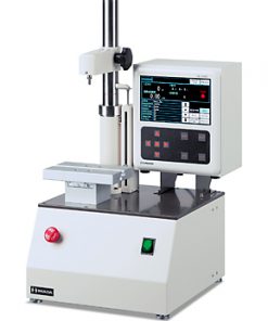
Terminal & applicator changer
Significant reduction in machine set up time
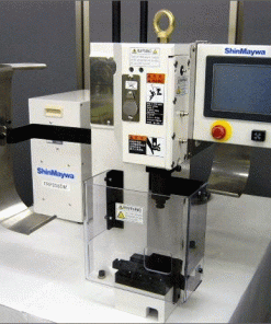
Simply set up the next terminals or applicators during the production. The applicator sliding plate also supports this job.

- The automatic wire changer, the terminal & applicator changing device are options.
Standard specification
| TRD401 | TRD401WPA Both-ends seal insertion | TRD401WPSA Single-end seal insertion | ||
|---|---|---|---|---|
| Max. processing capacity | Both-ends crimping 4,200 (pcs/h) | Both-ends crimping 3,900 (pcs/h) Both-ends seal insertion & both-ends crimping 2,600 (pcs/h) | Both-ends crimping 3,900 (pcs/h) Single-end seal insertion & both-ends crimping 2,600 (pcs/h) | |
| Conditions: Cut length 100 (mm); Machine speed set at max. | ||||
| Wire O.D. / Wire size | Standard | 1.0 – 3.0 (mm) / 0.22 – 2.0 (mm2) | ||
| Smaller gauge | 0.8 – 2.0 (mm) / 0.13 – 0.8 (mm2) | Contact us for details about “Smaller gauge” and “3mm2 setting” applications. | ||
| 3mm2setting | 1.5 – 4.0 (mm) / 0.5 – 3.0 (mm2) | |||
| Cut length | 60 – 20,000 (mm) | |||
| Strip length F&R sides | 0 – 17 (mm) At 0.1 (mm) intervals | |||
| Semi-strip length F&R sides | 1 – 25 (mm) At 0.1 (mm) intervals Max.insulation shifting length17 (mm) | |||
| Press force capacity | 24.5 (kN) | |||
| Crimping stroke | Standard 30 (mm) Optional 40 (mm) | |||
| Applicable terminal | Max. board thickness | (Copper alloy) 0.6 (mm) or less | ||
| Max. length | 25 (mm) Up to 30 (mm) possible, although with limited processing capacity between 25 and 30 (mm) | |||
| Seal insertion unit seal | – | O.D. φ8mm × Length 12mm or less; Tubular rubber*1 | ||
| Primary power source | 3-phase AC 200±20 (V) 50/60 (Hz) ; PC power source Single-phase AC 100V±14 (V) A single-phase 100V power tap for PC is available on the optional primary transformer. | |||
| Power consumption | 0.35 (kWh) | 0.41 (kWh) | 0.40 (kWh) | |
| Use a power source of at least 3kVA to allow for instantaneous current while power is on or at start up. | ||||
| Compressed air source | Pressure | 0.5 – 0.7 (MPa) | ||
| Consumed volume*2 | 0.15 (m3/min) (ANR) | 0.25 (m3/min) (ANR) | 0.20 (m3/min) (ANR) | |
| Including the volume consumed by parts feeders | ||||
| Operation screen | Display | LCD monitor | ||
| Language | Japanese / English / Spanish / Chinese (For other languages, please contact us.) | |||
| Input | Mouse and keyboard | |||
| Operator authorization | Up to 5 levels | |||
| Crimping monitor | ShinMaywa terminal crimping monitor as standard, with waveforms displayed in the lower part of the screen | |||
| Operating conditions | Temperature | 10 – 40 (℃) | ||
| Humidity | RH 40 – 60 (%) | |||
| Weight | Main body | 890 (kg) With optional equipment | 940 (kg) With optional equipment | 920 (kg) With optional equipment |
| Wire stacker | 2m model: 150 (kg) 3m model: 180 (kg) 5m model: 230 (kg) | |||
| Parts feeder | – | 25 (kg) / unit (including the cart) | ||
| PC stand with auxiliary wire holder | 30 (kg) | |||
| Other standard items | Bad wire chopper, paper coiler, wire straightener with a counter, terminal and overload sensor, wire joint sensor, wire sensor, wire overload sensor, a set of nozzles | |||
- For wire-seal combinations, please contact us.
- Air supply must be in the range from 0 to 30°C.
If there is a possibility of freezing, fully remove all moisture from the air supply using a drier, etc.
Remove oil and dust from the air supply using a filter or mist separator to avoid adverse effects on pneumatic equipment.
Dimensional outline drawing
For the TRD401, TRD401 WPA and TRD401 WPSA


